
LuwuDynamics/xgoduck_hardware
LuwuDynamics/xgoduck_hardware has 1,843 GitHub stars and 235 forks. GitHot measured +13 stars in 24 hours and +96 in 7 days. Last checked 2026-11-09 01:23 UTC. Last push 2026-10-30.
Build your own robot duck. XGO-Duck is a 3D-printable biped powered by Arduino UNO Q and 15 servos, adapted from Pollen Robotics' Microduck. Includes mechanical models, PCB designs, a BOM, and an assembly guide. Build it, explore its motion, and make it your own.
Measured star growth
- in 24h
- +13
- in 7 days
- +96
- in 15 days
- Update delayed
- in 1 month
- Update delayed
Net star changes over overlapping periods, not daily totals. Missing measurements are left blank. Stars measure attention, not software quality.
README.md
Original[!WARNING] ⚠️ CHARGING SAFETY — POWER SWITCH OFF
Always turn the power switch OFF before charging.
Keep it OFF throughout charging.If the adapter indicator turns green but the system will not power on:
If, after extended charging, the adapter indicator turns green but the system will not power on after the adapter is unplugged and the power switch is turned ON, check the battery pack's output with a multimeter.
The recovery procedure below applies only to a 2-series-cell lithium-ion pack rated 7.4 V nominal / 8.4 V maximum. Do not use this procedure for deeply discharged or damaged cells.
- Turn the power switch OFF, unplug the adapter, and disconnect the battery pack from the PCB.
- Use a regulated, current-limited external supply at 7.4 V or 8.4 V, with a 1 A or 2 A current limit that does not exceed the pack's specified charging current. Alternatively, use an adjustable DC bench supply with the voltage limit set to 7.4 V and the current limit set to 1 A. These are voltage and current limits, not a requirement to force a constant 1 A into the battery. An adapter's nameplate current rating alone is not a controlled charging current.
- With the recovery supply switched OFF, connect its positive and negative leads to the battery pack's matching protected charging terminals, checking polarity carefully. Do not bypass the protection board or connect directly to bare cells. Enable the supply for 10–20 seconds while monitoring the pack to attempt to release the protection cutoff. Then switch the supply OFF and disconnect it. Stop if there is abnormal heating or any other abnormal behavior. Confirm that the pack output has recovered; if it remains at 0 V, stop and contact the battery supplier or [email protected] rather than repeating the attempt.
- Once the output has recovered and the pack is operating normally, reconnect the battery to the PCB and reconnect the compatible charging adapter to resume normal charging. Keep the power switch OFF throughout charging.
[!WARNING] When testing and tuning servos, avoid stalling them as much as possible.

XGO-Duck
English · 简体中文
Build a robot duck. Explore how it moves. Make it your own.
A 3D-printable biped robot built around Arduino UNO Q and 15 serial servos.
Assembly guide · Bill of materials · Runtime · Training
A clean somersault · CyberBionic Maker
Meet XGO-Duck
XGO-Duck is a duck-shaped biped robot adapted by Luwu Dynamics from Pollen Robotics' Microduck. It combines a printable structure, fifteen Feetech 1910 servos, an Arduino UNO Q, and a custom expansion board with an IMU and servo interfaces.
This repository is the hardware starting point: print the parts, prepare the electronics, and assemble the robot. Companion repositories provide the onboard runtime and reinforcement-learning tools, connecting a physical build with motion experiments.
| Build | Run | Experiment |
|---|---|---|
| Print the body, legs, neck, head and soft parts. Assemble with the illustrated guide. | Configure and calibrate the robot through the companion runtime's browser interface. | Study the simulation, train policies and explore your own motions. |
| Hardware files | Onboard runtime | RL tools |
A closer look
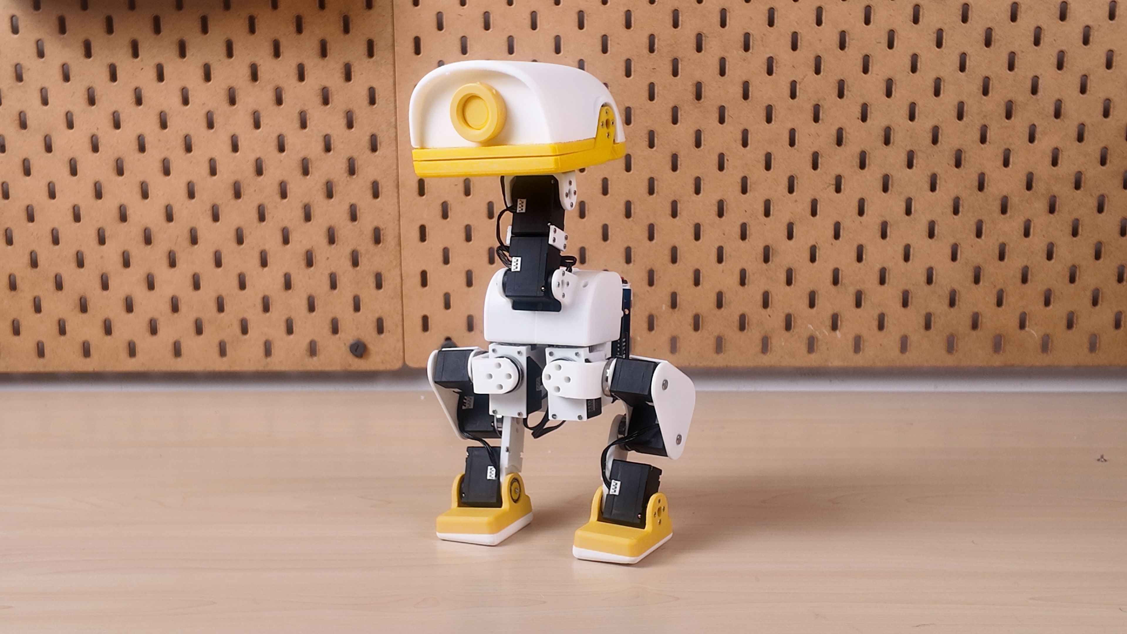
XGO-Duck prototype — printed parts, articulated legs, and a movable head and beak.
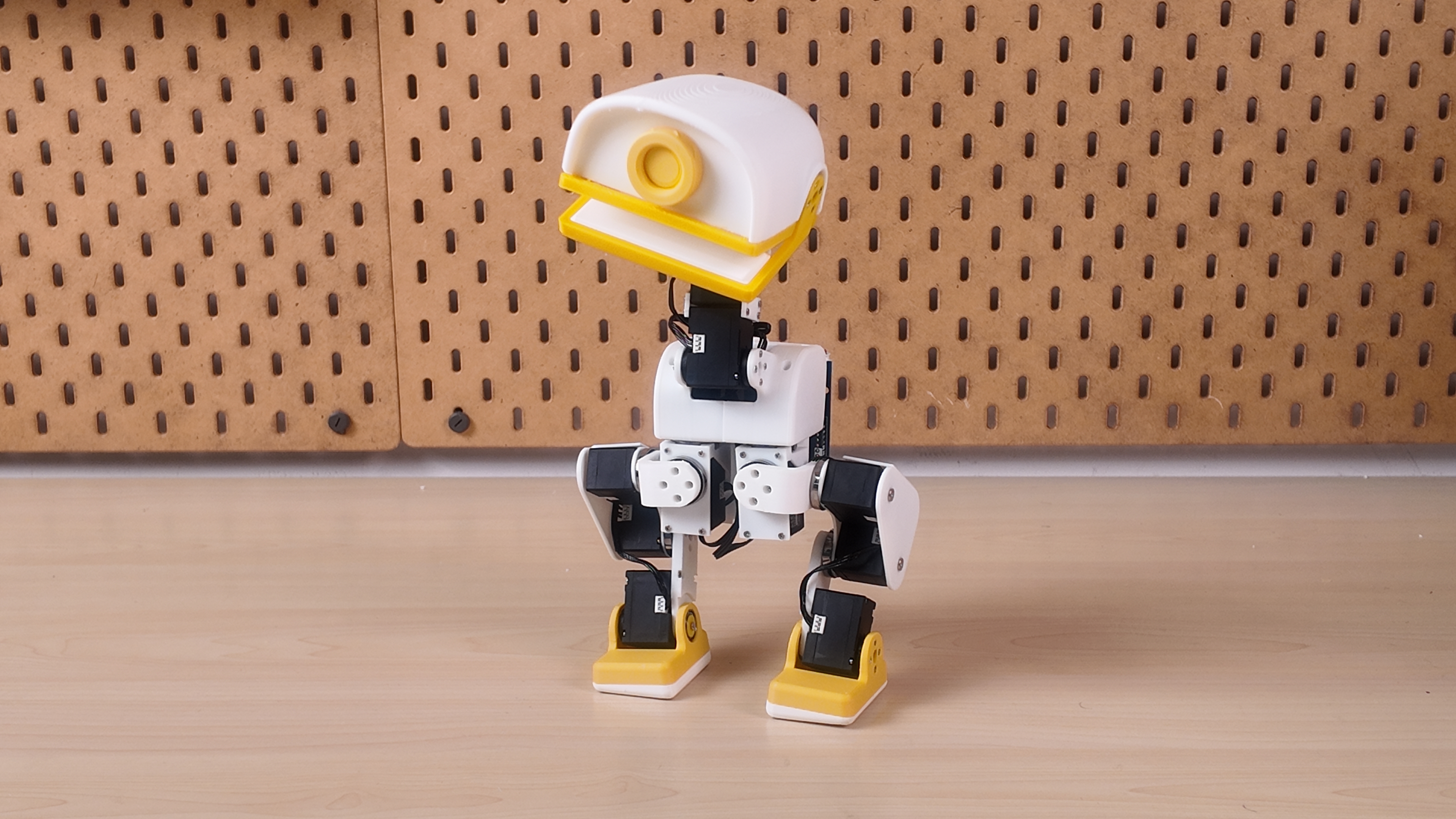 A movable head and beak Four neck/head joints and a separate mouth servo. |
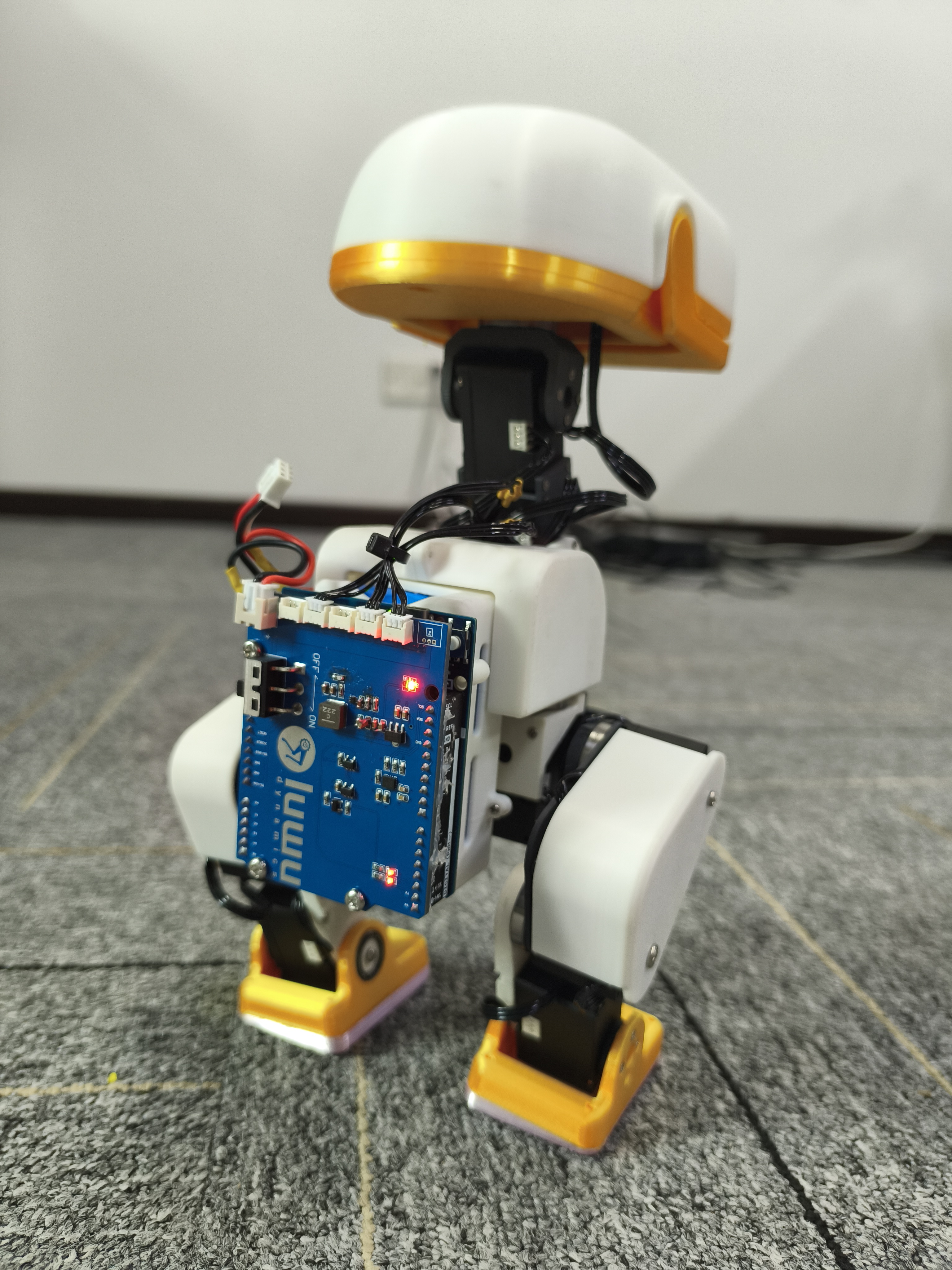 Electronics you can inspect Rear-mounted controller stack and accessible wiring. |
The photos show project prototypes. Follow the assembly guide and matching board files for your build revision.
Hardware at a glance
| Subsystem | What it uses | Role |
|---|---|---|
| Controller | Arduino UNO Q | Linux host for policy inference and web UI; STM32 MCU for servo and sensor communication |
| Actuation | 15 Feetech 1910 serial servos | 10 leg joints, 4 neck/head joints, and 1 mouth joint |
| Expansion board | Luwu UNO Q expansion board | Power distribution, servo connections and IMU integration |
| Motion sensing | QMI8658A 6-axis IMU | Acceleration and angular-velocity feedback |
| Structure | STL parts | Body, leg, neck and head components |
| Soft parts | TPU-designated STL files | Foot soles and mouth parts |
The motion policy outputs targets for 14 joints; the mouth servo is controlled separately. Component details and purchasing checks are collected in the BOM notes.
How the system connects
flowchart TD
    UI[Browser: setup, calibration and control] <--> HOST[UNO Q Linux: ONNX policy and web UI]
    RL[Training computer: simulation and RL] -->|Export ONNX policy| HOST
    HOST <-->|Arduino Bridge| MCU[UNO Q STM32: servo and IMU loop]
    MCU <-->|Serial bus| SERVOS[15 Feetech 1910 servos]
    IMU[QMI8658A IMU] -->|Sensor feedback| MCU
    BOARD[Custom expansion board] --- SERVOS
    BOARD --- IMU
This is a functional overview; use the board design and assembly documentation for electrical connections.
Start your build
Current board version: V1.1 (2026-10-26). Use the V1.1 design and production files. Previous files and wiring instructions are archived separately.
1. Prepare parts and electronics
Open the bill of materials for the robot purchasing list, supplier links and battery requirements, and PCBA/ for the expansion-board files. The robot BOM and PCB manufacturing BOM serve different purposes: a finished expansion board already includes its board-level components.
| Part | Quantity |
|---|---|
| Arduino UNO Q (2 GB / 4 GB) | 1 |
| Robot expansion board — Luwu Dynamics Store | 1 |
| Feetech 1910 servo with AMP 3-pin cable | 15 |
| Battery pack, listed as “18650 battery 8.4V” | 1 |
| 8.4 V Li-ion battery charger with 5.5 × 2.1 mm DC barrel plug (DC5521) | 1 |
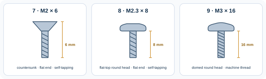
| M2 × 6 countersunk, flat-end self-tapping screw | 204 (200+4 for roller) |
| M2.3 × 8 flat-top round-head, flat-end self-tapping screw | 6 |
| M3 × 16 round-head machine screw | 4 |
| 10 × 15 × 3 mm bearing | 11 (3+8 for roller) |
| 16 × 22 × 4 mm bearing | 11 |
Quantities include the optional roller skates: 4 additional M2 × 6 screws and 8 additional 10 × 15 × 3 mm bearings. Confirm the pack, charger, connector polarity and power requirements using the component notes before sourcing or powering the build.
The expansion-board store page also offers a separate battery-and-charger option. Select Only Robot Driver Board for Arduino UNO Q for the board above; the bundle has not been verified against the battery and charger specifications in this list. See the purchasing notes.
For easier purchasing, Luwu Dynamics offers an official XGO-Duck electronics kit containing all components in the BOM except the Arduino UNO Q.
Identify the three fasteners before ordering. Items 7 and 8 are self-tapping screws with flat ends. Items 8 and 9 share the same rounded side profile; item 8 has a flat top, while item 9 has the gently domed top shown in the photo below and a machine thread. The following shape guide is illustrative. See the product photo and size references in the BOM.
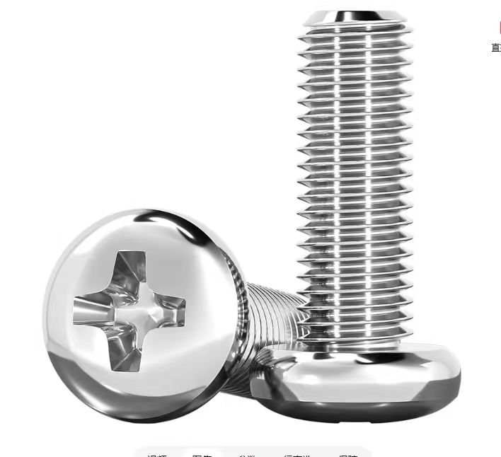
Item 9 has the domed top shown here. Item 8 has the same rounded sides but a flat top. The photo is a head-style reference, not a size or thread specification.
2. Print the structure
Download the models from structure/. The filenames carry useful assembly information:
| Filename pattern | Meaning | Example |
|---|---|---|
2x_ |
Print two copies | 2x_shank.stl |
4x_ |
Print four copies | 4x_tire.STL, 4x_tire_axis.STL |
left_ / right_ |
Separate left and right parts | left_foot.stl, right_foot.stl |
tpu |
Flexible part | 2x_foot_bottom_tpu.stl, mouth_up_tpu.stl |
Use the print inventory to track parts. Test a servo mount and bearing fit before printing the full set; a complete validated print profile is still to be documented.
For the optional roller skates, print 2x_tire_support.STL × 2, 4x_tire.STL × 4 and 4x_tire_axis.STL × 4.
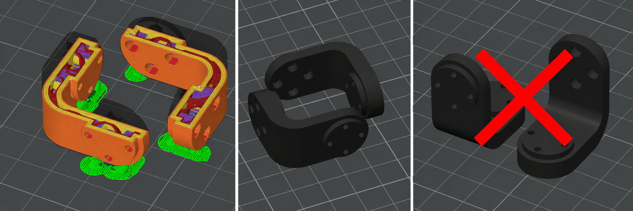
Print orientation matters: place the part as shown before slicing — lay it flat with the open channel facing up and the two end tabs resting firmly on the build plate. Use 4 walls and 13% Gyroid infill. Do not stand it upright, lay it on its side, or flip it over, and do not rely on the slicer's auto-arrange. Otherwise the holes may deform and the ends may break. After slicing, check the preview against the reference image before printing.
3. Configure servos and assemble
Prepare each servo's ID and center position using the runtime setup instructions, then follow Assembly_Guide.pdf.
| Assembly reference | Focus |
|---|---|
| Page 1 | Servo ID placement |
| Pages 2–5 | Shaft preparation, initial structure and cable routing |
| Pages 6–15 | Legs, feet and soles |
| Pages 16–23 | Head and neck mechanisms |
| Pages 24–25 | Final assembly |
The build guide adds preparation and inspection checkpoints. Configure one servo at a time, label its ID, and leave cable clearance through each joint's movement.
4. Calibrate and bring it to life
Install the onboard runtime, verify servo and IMU feedback, and complete calibration with the robot supported. Start with the default pose before motion trials.
The runtime includes walk, get-up and pick policies, plus separate mouth control. Their behavior depends on the assembled hardware, calibration and test conditions. Using the bundled policies does not require training a new model.
Hardware files
| Path | Contents |
|---|---|
| Assembly_Guide.pdf | 25-page illustrated assembly reference |
| BOM.md | Whole-robot purchasing list, supplier links and battery reference image |
| structure/ | Printable STL models |
| V1.1 schematic | Altium schematic source |
| V1.1 BOM · Placement data | Board materials and placement coordinates |
| V1.1 production files | Fabrication notes, Gerber and drill files |
| V1.1 silkscreen layout | PDF reference |
| V1.1 DWG · STEP model | Drawing and 3D model |
| Previous version archive | Complete previous files and historical instructions |
| docs/ | Build, printing, BOM and troubleshooting notes |
From hardware to your own behavior
| Repository | Purpose |
|---|---|
| xgoduck_hardware | Mechanical parts, electronics, BOM and assembly |
| xgoduck_runtime_arduino | UNO Q firmware, policy execution, browser setup and control |
| xgoduck_rl | Simulation, reinforcement-learning training and policy export |
Keep the hardware, runtime and policy revisions together in your build record. This makes it easier to reproduce a working configuration and diagnose changes.
Origins and contributions
XGO-Duck builds on Microduck and microduck_rl by Pollen Robotics. The duck form, 15-servo arrangement and policy joint order originate in that work. Luwu Dynamics' adaptation focuses on Arduino UNO Q, Feetech 1910 servos, the custom expansion board, and the matching software/model integration. See origins and adaptations.
Build reports, tested print settings, clearer assembly photos and reproducible fixes are welcome. Read CONTRIBUTING.md or open an issue.
For reuse terms, consult LICENSING.md and the applicable file-level notices. Contact: [email protected].
Explore related projects
ytdl-org/youtube-dl
Command-line program to download videos from YouTube.com and other video sites
141,500 starsexcalidraw/excalidraw
Virtual whiteboard for sketching hand-drawn like diagrams
135,331 starsgodotengine/godot
Godot Engine – Multi-platform 2D and 3D game engine
119,840 starsmrdoob/three.js
JavaScript 3D Library.
117,905 stars