
n-IA-hane/esphome-audio-stack
n-IA-hane/esphome-audio-stack has 31 GitHub stars and 14 forks. GitHot measured 0 stars in 24 hours, +2 in 7 days, and +3 in 15 days. Last checked 2026-11-22 13:19 UTC. Last push 2026-11-20.
측정된 스타 증가
- in 24h
- 0
- in 7 days
- +2
- in 15 days
- +3
- in 1 month
- 기록 수집 중
서로 겹치는 기간의 순증가량이며 일별 합계가 아닙니다. 측정값이 없으면 비워 둡니다. 스타는 관심도를 나타내며 품질을 보장하지 않습니다.
소개
Full-duplex audio for ESPHome on ESP32-S3 and ESP32-P4: shared or separate I2S buses, TDM, AEC/AFE and echo-cancelled microphone audio for wake word, Voice Assistant and calls.
창작 및 미디어README.md
OriginalESPHome Audio Stack
Developed and maintained by n-IA-hane, with community contributions and support. ❤️ Sponsor the project
Stable release 2026.11.0 uses the coordinated main sources.
Capture the microphone and play the speaker at the same time, even on a single shared I2S bus. Feed echo-cancelled microphone audio to Micro Wake Word, Voice Assistant and calls through their normal ESPHome interfaces.
Audio Stack coordinates the I2S input/output and supported hardware codecs. It supports a single shared bus, separate RX/TX buses, and supported TDM microphone layouts. A second I2S bus is not required.
With esp_aec or esp_afe enabled, the processor reduces the local speaker's
echo in the microphone signal before that signal reaches its consumers.
For example, while the device plays music or a spoken reply:
- Micro Wake Word receives processed microphone audio, helping it detect your wake word while playback continues.
- Voice Assistant receives that same processed input for speech-to-text, reducing the device's own playback in what it sends for recognition.
- A VoIP call sends processed microphone audio to the other party, reducing the echo of their voice returning through your speaker and microphone.
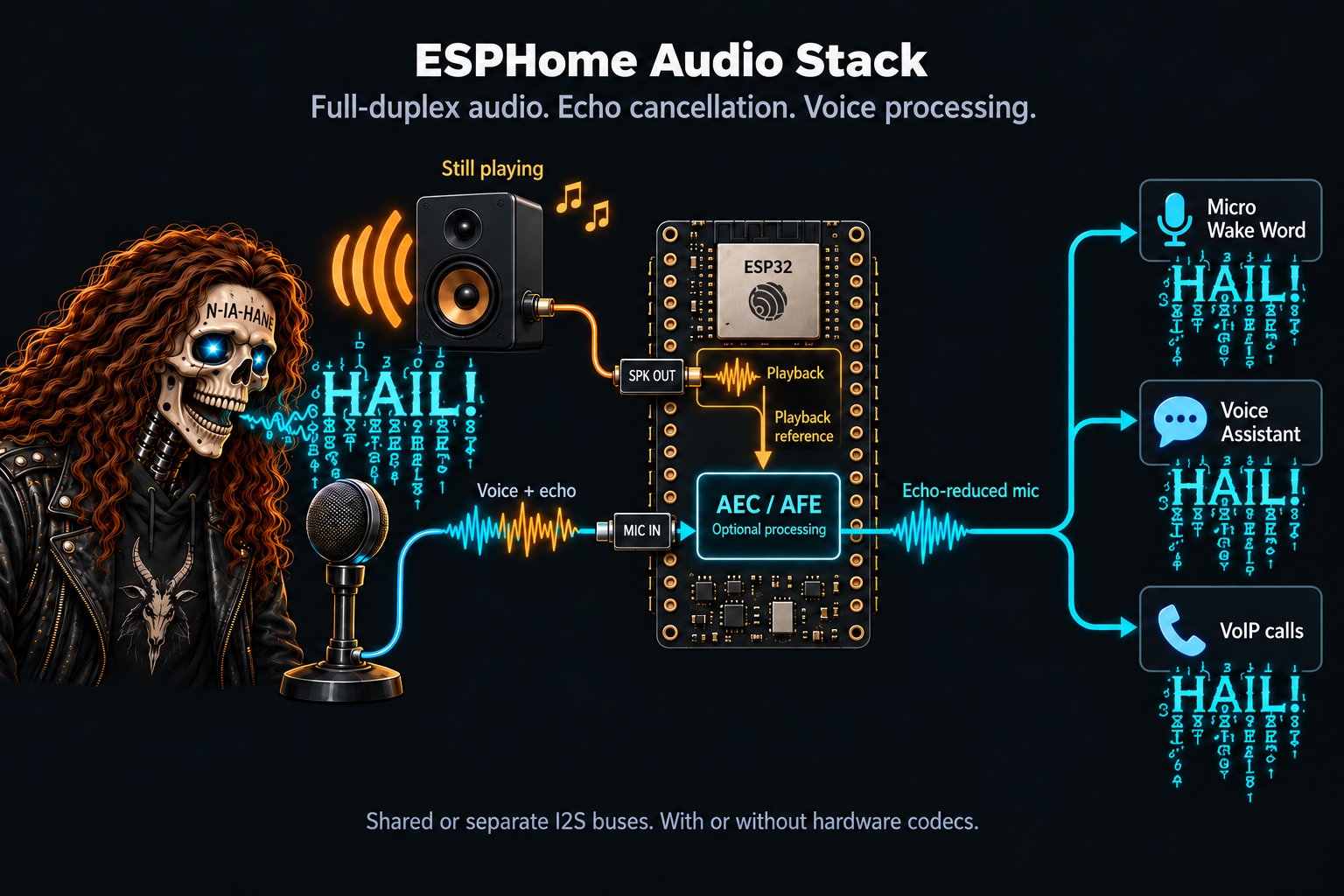
AEC reduces echo in microphone capture while the speaker keeps playing. Correct reference routing, levels and microphone/speaker placement still matter; cancellation and wake-word detection must be checked on the finished device.
The standard ESPHome microphone delivers the processed signal directly to its consumers. Audio Stack works with ESPHome's speaker, mixer, resampler and player components. Your runtime configuration still decides which consumers run together and when Assist may start a session. For devices that need only capture/playback, omit the optional processor.
Use the standard audio, resampler, mixer, player, Voice Assistant, Micro Wake Word and OTA providers included in ESPHome. This repository supplies the bus, codec and optional processing components; it does not override those ESPHome providers.
Previous stable 2026.10.2 | Changelog
Use ESPHome 2026.10.0 or newer, ESP-IDF, and an ESP32-S3 or ESP32-P4 with PSRAM. Select the correct PSRAM mode and pins from your board's schematic.
Optional microphone downmix, analog tuning and PCM capture are available for board development. Existing profiles keep their delivery and gain defaults; diagnostics remain off until explicitly requested.
Choose a complete device or a custom audio path
| Your goal | Starting point | Expected result |
|---|---|---|
| Use a supported board for calls, Assist or music | A maintained Intercom device YAML | Board wiring, audio and application consumers are composed together |
| Bring up your own microphone and speaker | The basic I2S example | Public microphone/speaker endpoints for your consumer or player |
| Reduce playback echo in microphone capture | AEC, after raw capture/playback work | Processed microphone audio using a correctly routed playback reference |
| Use a codec loopback or several microphones | Stereo reference or TDM | Channel roles matching the physical board wiring |
| Add the full speech front end | AFE | The selected speech-processing stages on the existing audio path |
| Combine music, voice replies and calls | Rates and playback sources | Shared output with the required resamplers/mixer and application coordination |
For a maintained device, start with its defaults and the
progressive package examples.
The maintained profiles use firmware_features to select consumers;
you do not need to construct this low-level audio path again. The selected
AFE/AEC/native backend is a separate hardware/profile choice.
For a custom build, the numbered sections grow from capture/playback to concurrent applications. Bus layouts, codec reference and TDM are hardware alternatives, not mandatory upgrades to apply in sequence. Stop when your device has the functionality it needs.
Read in order for a first custom build, or jump to the relevant hardware:
- Start with a microphone and speaker
- One bus or two
- Add a hardware codec
- Add echo cancellation
- Use the codec stereo channel as a reference
- Use TDM for multiple input channels
- Add AFE speech processing
- Combine different rates and playback sources
- Tune and diagnose the finished device
For a wiring-focused view, see Microphone wiring and delivery, illustrated: single mic, stereo L/R, TDM, analog codecs, downmix and separate RX/TX buses.
1. Start with a microphone and speaker
Start with Audio Stack alone; add processing and application components as needed. This example deliberately uses 48 kHz for the physical bus and speaker and 16 kHz for the public microphone. Audio Stack converts capture from 48 to 16 kHz. These are separate choices: the hardware does not become a 16 kHz speaker just because a speech processor consumes a 16 kHz microphone. For example, an I2S MEMS microphone and an I2S amplifier can share clock wires while using separate data wires:
                              ┌──► Microphone BCLK / WS
ESP BCLK / WS ────────────────┤
                              └──► Amplifier BCLK / WS

Microphone DATA ─────────────► ESP DIN  ──► microphone consumers
Amplifier DATA ◄────────────── ESP DOUT ◄── speaker PCM
BCLK clocks individual bits. WS (also called LRCLK) identifies the audio frame and its left/right slots. DIN and DOUT are named from the ESP's point of view. The microphone and amplifier must accept the same clock rate and frame format. This arrangement works directly with compatible I2S microphone and amplifier modules.
The complete generic example supplies the ESPHome board, PSRAM and component declarations. From a repository checkout, validate it with:
esphome config examples/00-generic-i2s-duplex.yaml
It uses a local component source. If copying it outside the repository, replace that source as instructed in the example. This first example declares audio endpoints; it has no network, Voice Assistant or player, and does not record or play anything by itself. Use a complete device profile for a ready-to-use application. Every arrow below is a valid YAML comment, so the example remains copyable. Its audio section is:
esp_audio_stack:                 # <-- One capture/playback hardware owner.
  sample_rate: 48000             # <-- Physical bus and speaker: 48 kHz.
  output_sample_rate: 16000      # <-- Public mic: convert 48 kHz to 16 kHz.
  bits_per_sample: 32            # <-- Captured I2S sample width.
  slot_bit_width: 32             # <-- Width of each physical I2S slot.
  rx_slot_mode: stereo           # <-- Read both Left/Right bus slots.
  mic_channel: left              # <-- Keep the slot selected by the mic's L/R pin.
  i2s_bclk_pin: GPIO6            # <-- Shared BCLK output to microphone and amp.
  i2s_lrclk_pin: GPIO7           # <-- Shared WS/LRCLK frame-clock output.
  i2s_din_pin: GPIO4             # <-- Mic DATA enters the ESP here.
  i2s_dout_pin: GPIO8            # <-- Speaker DATA leaves the ESP here.

microphone:                      # <-- Mono, 16-bit PCM at 16 kHz.
  - platform: esp_audio_stack    # <-- Use the parent's capture and conversion.
    id: board_mic                # <-- Input ID for Assist, MWW or VoIP.

speaker:                         # <-- PCM destination for playback.
  - platform: esp_audio_stack    # <-- Use the same parent's output hardware.
    id: board_speaker            # <-- Reference this ID from a player or mixer.
    sample_rate: 48000           # <-- Incoming playback PCM must be 48 kHz.
    bits_per_sample: 16          # <-- Public PCM is 16-bit, bus slots are 32-bit.
    num_channels: 1              # <-- One mono playback channel.
The resulting rates are visible without inspecting another package:
48 kHz playback PCM ► [board_speaker] ► I2S TX at 48 kHz ► amplifier

Microphone ► I2S RX at 48 kHz ► [Audio Stack: 48 ► 16 kHz]
                                             │
                                             └──► [board_mic: 16 kHz]
sample_rate sets the bus/playback rate. output_sample_rate sets the mic
rate after conversion. Neither is a fixed project-wide 16 kHz limit. The
configured hardware must support the bus rate; capture conversion accepts
integer downsampling ratios up to six. The example's 48-to-16 kHz ratio is three.
bits_per_sample and slot_bit_width describe bus samples and slots,
not the sample rate. The public mic and speaker interfaces use 16-bit PCM.
Configure the mic rate on the parent through output_sample_rate, not on the
microphone: child, whose format comes from the parent.
The optional standalone AEC and AFE paths process this 16 kHz capture while playback stays at 48 kHz. This first example has no processor yet, so converted capture still includes speaker echo. The complete AEC example adds the processor and playback reference for a codec board.
If a playback source supplies 16 kHz PCM, use a speaker resampler to convert it
to 48 kHz before board_speaker; output_sample_rate does not resample playback.
The playback-source section
shows where that resampler and a mixer belong.
One stack per device: the component currently supports a single
esp_audio_stack instance on each ESP. Its microphone, speaker, level sensors,
numbers and AEC switch find that instance automatically, so esp_audio_stack_id
is optional and omitted in these examples. One instance can manage a shared bus
or separate RX/TX buses; using two buses does not mean declaring two stacks.
The stack declaration and its actions can also omit IDs. Add an explicit stack
id only when your custom lambdas or other named references need it.
These are example GPIOs for an S3 prototype, not universal board pins. Set the
microphone's L/R selection to match mic_channel, and configure the amplifier's
channel selection according to its datasheet. This is standard I2S, not PDM.
The microphone exposes mono signed 16-bit PCM, even when the physical bus uses 32-bit slots. The speaker also accepts signed 16-bit PCM at the bus rate. A consumer such as Voice Assistant starts capture; a playback component writes speaker samples. Add a recording, playback or calling component to use these audio endpoints.
Without processor_id, capture contains the microphone signal with the
configured conversion and gain, including any sound from the local speaker.
For microphone-only or speaker-only hardware, declare only the public platform
you use and omit the unused data pin. Internal clock generation may still be
needed even in a microphone-only configuration.
Choose a complete microphone-processing example
The two-microphone examples make two different choices explicit: AFE/SE-BSS receives both microphones separately, while standalone AEC receives their mono average. The capture wiring stays the same within each pair.
| Input and processing | Complete example |
|---|---|
| One microphone, standalone AEC | 02: single-mic AEC |
| One microphone, AFE | 03: single-mic AFE |
| Two TDM microphones, separate channels to AFE/SE-BSS | 06: dual-mic AFE/BSS |
| Two Left/Right I2S microphones, separate channels to AFE/SE-BSS | 07: codec-free dual-mic AFE/BSS |
| Two TDM microphones, mono downmix to AEC | 04: dual-mic downmix and AEC |
| Two Left/Right I2S microphones, mono downmix to AEC | 05: codec-free downmix and AEC |
Averaging before a single-microphone AFE remains an optional alternative, described in the wiring guide. It does not retain separate inputs for SE/BSS. The GPIOs and codec feedback connections in these examples are illustrative; use your board's actual wiring.
2. One bus or two
Both supported chips can capture and play simultaneously on one shared I2S bus. Two separate buses are an optional wiring arrangement.
| Chip | Duplex on one shared bus | Two separate buses (optional) | TDM on one shared bus |
|---|---|---|---|
| ESP32-S3 | Yes | Yes | Yes |
| ESP32-P4 | Yes | Yes | Yes |
The ordinary shared-bus configuration uses one I2S peripheral.
One shared bus saves an I2S peripheral and clock pins. Audio Stack owns both
RX and TX, so they are configured together. Do not also assign those pins or
that peripheral to a native i2s_audio component.
Two buses suit boards where the microphone and amplifier use separate clock wires. Replace the top-level I2S pin fields in the first example with:
esp_audio_stack:                 # <-- One owner also manages two separate buses.
  sample_rate: 48000             # <-- Both physical buses and speaker: 48 kHz.
  output_sample_rate: 16000      # <-- Convert microphone capture to 16 kHz.
  bits_per_sample: 32            # <-- Microphone bus sample width.
  slot_bit_width: 32             # <-- Physical I2S slot width.
  rx_slot_mode: stereo           # <-- Capture both Left/Right slots.
  mic_channel: left              # <-- Select the mic's occupied slot.
  rx_bus:                        # <-- Separate capture bus.
    i2s_num: 0                   # <-- First I2S peripheral.
    i2s_bclk_pin: GPIO6          # <-- Microphone bit-clock output.
    i2s_lrclk_pin: GPIO7         # <-- Microphone frame-clock output.
    i2s_din_pin: GPIO4           # <-- Microphone data input.
  tx_bus:                        # <-- Separate playback bus.
    i2s_num: 1                   # <-- Different I2S peripheral.
    i2s_bclk_pin: GPIO9          # <-- Amplifier bit-clock output.
    i2s_lrclk_pin: GPIO10        # <-- Amplifier frame-clock output.
    i2s_dout_pin: GPIO8          # <-- Amplifier data output.
Both bus blocks are required and their port numbers must differ. This backend uses the same configured sample rate for both. Split-bus mode supports standard I2S; TDM uses the shared-bus configuration. The current schema allows two I2S ports on S3 and three on P4.
If native ESPHome audio already supports your independent devices and you do not need this backend's shared codec or reference handling, it remains a valid choice. A device with hardware echo cancellation, such as an XMOS voice front end, may not need a software processor here at all.
3. Add a hardware codec
A hardware codec converts analog microphone signals to digital samples (ADC) and digital playback to analog output (DAC). This is different from an audio file codec such as MP3 or FLAC. Audio Stack handles PCM and hardware codec control; a media player/decoder handles compressed files.
The I2C connection configures the codec. I2S carries audio. Some codecs also require MCLK, a higher-frequency master clock:
ESP I2C SDA/SCL ◄─────────────► Codec registers (gain, format, volume)
ESP MCLK/BCLK/WS ─────────────► Codec clocks
ESP DIN ◄────────────────────── Codec ADC ◄─── microphone
ESP DOUT ─────────────────────► Codec DAC ───► amplifier ───► speaker
Use the ES8311 audio-only example for
the declaration structure. Replace its GPIOs, I2C address and clock settings
with those of your board. The codec block is added to esp_audio_stack:
codec:                           # <-- Add inside the existing esp_audio_stack.
  input:                         # <-- Analog microphone capture through the ADC.
    type: es8311                 # <-- Supported hardware codec chip.
    address: 0x18                # <-- Its actual I2C control address.
  output:                        # <-- Playback through the DAC.
    type: es8311                 # <-- Same codec's output side.
    address: 0x18                # <-- Same chip and control address.
The driver, through Espressif esp_codec_dev, owns codec configuration. Avoid
boot lambdas that rewrite the same registers behind its back.
ES8311, ES8388, ES8374 and ES8389 are supported input/output codec choices; ES7210 is input-only. Declaring a supported chip cannot compensate for incorrect wiring, amplifier enable polarity or an incompatible board clock arrangement.
4. Add echo cancellation
Full duplex means capture and playback can run together. It does not mean the microphone stops hearing the speaker.
An acoustic echo canceller (AEC) receives the microphone signal and a playback reference. It estimates how playback reaches the microphone through the speaker, enclosure and room, then uses that estimate to reduce the echo. Clipping, the wrong reference channel or excessive delay can prevent useful cancellation.
Playback PCM ──► speaker path ─────────────────────► loudspeaker
                     │
                     └──► reference ────┐
                                        │
                                        ▼
Microphone ──► capture ─────────────► [AEC] ──► processed microphone
Add esp_aec to your external_components list, declare it, and add
processor_id: aec to the existing audio stack:
esp_aec:                         # <-- Optional standalone echo canceller.
  id: aec                        # <-- Bind with esp_audio_stack.processor_id: aec.
  sample_rate: 16000             # <-- Matches output_sample_rate, not the 48 kHz bus.
  mode: sr_low_cost              # <-- Speech/wake-word-oriented starting profile.
  filter_length: 4               # <-- ESP-SR tuning parameter (1-8), not milliseconds.
Use output_sample_rate: 16000 if the bus runs faster: the processor works at
16 kHz. Complete AEC example.
Without hardware feedback, the reference comes from the software playback
path. The default aec_reference: ring_buffer retains reference samples in a
bounded queue. aec_reference_buffer_ms sets its capacity; actual delay
depends on the queued samples. previous_frame uses the preceding playback frame with less
storage; use it only when cancellation is satisfactory on the real device.
Start with sr_low_cost for a device that also listens for a wake word.
Communication-oriented voip_* and fd_* modes may reduce residual echo more
aggressively, but can also affect recognition during playback. Choose between low_cost and high_perf by measuring cancellation, recognition
and resource use on your device.
See the AEC reference for modes and
runtime reconfiguration.
The standalone component defaults to sr_low_cost. Maintained Intercom FULL
profiles instead start in SR HIGH and offer SR LOW/HIGH, preserving speech for
wake-word recognition during playback. VoIP-only profiles also offer FD. Those
preset choices do not remove the standalone component's other supported modes.
5. Use the codec stereo channel as a reference
In ES8311 digital-feedback mode, the left slot carries the microphone ADC and the right slot carries DAC playback feedback. Audio Stack separates these two roles before processing:
ES8311 I2S RX frame
┌──────────────────────┬──────────────────────┐
│ Left: microphone ADC │ Right: DAC reference │
└───────────┬──────────┴───────────┬──────────┘
            │                      │
            │                      │
            └───────► [AEC] ◄──────┘
                        │
                        ▼
                 mono microphone
On the ES8311 example, add these fields to the existing esp_audio_stack block:
num_channels: 2                  # <-- Capture the codec's two physical slots.
use_stereo_aec_reference: true   # <-- Separate microphone and DAC feedback.
reference_channel: right         # <-- Right carries playback, not another mic.
Set no_dac_ref: false in both the ES8311 input and output codec blocks to
request this feedback route. The processor still uses processor_id: aec (or
an AFE instance). num_channels describes the bus; the public microphone
continues to deliver mono audio.
Do not enable this mode for two ordinary stereo microphones. It would treat
one microphone as playback reference. For two MEMS microphones use
rx_mic_slots, described below. Likewise, another stereo codec does not
necessarily expose the ES8311 feedback arrangement.
Digital feedback avoids having to reconstruct playback timing from a software queue. Cancellation must still account for the physical amplifier, speaker and enclosure.
6. Use TDM for multiple input channels
TDM carries several numbered slots in each frame instead of just left/right. A board with an ES7210 ADC can place two microphones and a physical playback feedback connection into different slots. The board schematic determines which ADC input is wired to the feedback; a YAML option cannot create that connection.
Example for a board wired with this physical arrangement:
RX frame (4 physical slots):
┌────────────┬────────────┬────────────┬────────────┐
│ 0: mic A   │ 1: ref     │ 2: mic B   │ 3: unused  │
└─────┬──────┴─────┬──────┴─────┬──────┴────────────┘
      │            │            │
      └────────────┴────────────┴──► select and convert ──► AFE

TX frame (4 physical slots):
┌────────────┬────────────┬────────────┬────────────┐
│ 0: audio   │ 1: unused  │ 2: unused  │ 3: unused  │
└─────┬──────┴────────────┴────────────┴────────────┘
      └──► DAC ──► speaker
After choosing the board's pins and codecs, this fragment selects that layout:
tdm_total_slots: 4               # <-- Four physical slots per bus frame.
tdm_mic_slots: [0, 2]            # <-- Two microphone inputs, in this order.
use_tdm_reference: true          # <-- Use a physically wired feedback input.
tdm_ref_slot: 1                  # <-- Feedback occupies slot 1, not a mic slot.
tdm_tx_slot: 0                   # <-- Send speaker PCM through output slot 0.
These fields select the inputs inside esp_audio_stack. Pair them with the
two-microphone AFE configuration in the next section.
For a single TDM microphone, use tdm_mic_slots: [0] or tdm_mic_slot: 0 with
hardware-reference mode, not both forms together.
Slot numbers always refer to the physical frame. The driver packs selected
slots into DMA memory, and Audio Stack maps them back to their configured roles.
In the illustrated layout, RX stores three selected slots and TX one; the bus
still has four physical slots. Do not change tdm_total_slots to three or
renumber slot 2 to save memory. A diagnostic sensor for slot 3 causes that slot
to be captured as well.
TDM and AEC are separate decisions. TDM with tdm_mic_slots can also use a
software playback reference when no physical reference is wired. Hardware
stereo feedback and hardware TDM feedback cannot be enabled together.
7. Add AFE speech processing
Use esp_afe instead of esp_aec when you need additional voice processing.
Include [esp_audio_stack, esp_afe] in external_components, and set the
existing stack's processor_id to the AFE ID. Do not declare both processors.
| Function | What it addresses | Setup requirement |
|---|---|---|
| AEC | Echo from the device's playback | A correctly selected playback reference |
| NS, noise suppression | Background noise in speech capture | Good microphone placement or unclipped input |
| VAD, voice activity detection | Whether speech is present | Optional activity detection for voice-aware consumers |
| AGC, automatic gain control | Variation in speech level | Correct ADC gain; it cannot restore clipped samples |
| SE/BSS, two-microphone speech enhancement | Uses both microphones to improve speech separation | A second real microphone and the correct channel layout |
A single-microphone starting point is:
esp_afe:                         # <-- Optional speech-processing front end.
  id: afe                        # <-- Bind with esp_audio_stack.processor_id: afe.
  type: sr                       # <-- Speech-recognition-oriented AFE profile.
  mode: low_cost                 # <-- Lower processing cost starting point.
  mic_num: 1                     # <-- One delivered mic channel, excluding REF.
  aec_enabled: true              # <-- Reduce echo using the playback reference.
  ns_enabled: true               # <-- Reduce microphone background noise.
  agc_enabled: true              # <-- Adjust speech level automatically.
  vad_enabled: false             # <-- Optional speech-activity detection is off.
Complete single-mic AFE example. The public microphone now provides processed mono audio to its consumers. Disabling the parent stack's processor switch deliberately bypasses processing; disabling just the AFE's AEC stage leaves the other enabled stages in place. If an enabled processor is temporarily unavailable, the stack emits silence instead of switching unexpectedly to raw microphone audio.
Two microphones, with or without TDM
Set mic_num: 2 and se_enabled: true on the AFE, and keep
mic_mix: passthrough on Audio Stack. Choose one capture layout:
- TDM ADC:
tdm_mic_slots: [0, 2], using the board's actual slot numbers. - Standard I2S MEMS pair:
rx_slot_mode: stereoandrx_mic_slots: [left, right]. The microphones must share the data line correctly, with one strapped left and the other right. Use a software reference when there is no hardware reference input.
Complete examples: TDM with AFE/BSS or Left/Right I2S with AFE/BSS. For the same wiring with mono downmix and standalone AEC, use 04 or 05, respectively.
The two input microphones are processed into one public microphone stream. The first configured microphone is also the primary channel when processing is bypassed. See STD dual-mic configuration.
AFE names its internal channels M (microphone), R (reference) and N
(unused padding). The default is MR for one microphone and MMR for two.
input_format: MMNR inserts padding inside the AFE input. Physical capture
still uses the two microphone slots and the configured reference source.
Single- and dual-mic configurations use GMF feed/fetch tasks. Audio Stack supplies bounded input blocks; the AFE assembles its required processing frames and returns processed samples through the output stream. AFE processing frames, I2S DMA descriptors and VoIP packets each have their own size and timing.
With two microphones, ESP-SR prioritizes SE/BSS over its single-mic noise suppression stage. Optional post-AFE AGC uses a separate 10 ms processing block. AEC and VAD can be changed through the running AFE; changing NS, AGC or the AFE mode rebuilds processing and can briefly interrupt microphone output. Set the normal operating configuration at boot rather than repeatedly rebuilding it in an automation. AFE settings and controls.
8. Combine different rates and playback sources
sample_rate is the physical bus and speaker rate. output_sample_rate is the
microphone rate after conversion. For example, 48 kHz playback and 16 kHz voice
capture share a 48 kHz bus; only the microphone/reference path is downsampled.
Supported conversion uses integer ratios up to six, not arbitrary input/output
rate pairs. Omitting output_sample_rate keeps the bus rate.
Media / TTS ──► resampler ────┐
                              ├──► mixer ──► 48 kHz speaker ──► I2S TX
Call audio ──► resampler ─────┘

I2S RX ──► select mic/reference ──► 48-to-16 kHz ──► [AEC / AFE]
                                                          │
                                                          └──► 16 kHz microphone
Declare rates on the parent Audio Stack. Use an ESPHome resampler before the hardware speaker for sources at another rate. A mixer combines playback sources, while the player or runtime controller decides whether an announcement should interrupt music. Audio Stack handles the resulting capture and playback.
Sample rate describes samples per second; slot width describes bits per bus slot. A 32-bit I2S bus can carry audio exposed as 16-bit PCM. Choose rates supported by the hardware and consumers. Upsampling preserves the source bandwidth while adapting it to the playback rate.
Resampler and mixer example. Playback-completion callbacks report samples delivered through I2S and propagate to compatible mixer/resampler consumers. Preserve that feedback when adding synchronized playback such as Sendspin.
9. Tune and diagnose the finished device
First prove microphone capture and speaker playback independently. Then add processing, and finally concurrent music, voice commands and calls. A device that plays TTS once has not yet demonstrated stable full-duplex operation.
| Observation | Check first |
|---|---|
| Silent mic or speaker | Wiring, selected slot, codec initialization, amplifier enable and whether a consumer started the stream |
| Other party hears their voice back | Reference activity, reference channel, clipping and enclosure coupling |
| Quiet microphone | Codec ADC gain, then software mic gain; compare at the same distance and level |
| Distorted loud speech | Lower gain before the stage that clips; post-processing cannot reconstruct lost samples |
| Clicks or gaps | Capture/processing/playback timing, queue pressure and largest free internal block |
| Wake word unreliable during playback | Reference correctness and AEC mode, then measured recognition on the enclosure |
Hardware microphone gain acts before digital processing. input_gain scales
mic input before the processor; the software mic_gain control scales its
output. 0 dB is unity gain, not mute. Speaker volume changes playback and
must not be used as a substitute for fixing microphone gain.
Set gains in the order the signal passes through them
- Check raw microphone and reference levels with the intended speaker volume. If the microphone ADC clips, reduce its hardware gain. Lowering software gain after capture cannot recover those samples. Keep the reference's own channel/gain configuration appropriate for its physical tap.
- For an ES8311 and an external amplifier, set
codec.output.pa_gainfrom the circuit's gain in dB. It defaults to 0 and is passed to Espressif's hardware calibration, not added as a software boost. Do not copy another board's value. Correcting it can change loudness at the same volume percentage. - Compare the caller's recorded return with AEC off and on, using the same playback, volume and microphone gain. Check actual PCM as well as packet continuity. Account for any configured in-call music ducking.
- Set the post-processor Mic Gain with someone speaking near the microphone.
Its optional
initial_valueapplies only when no saved user value exists; upgrading does not overwrite the previous setting. Check quiet speech, loud speech and simultaneous speech/playback separately.
A quiet return during speaker-only playback is expected with effective AEC. It does not prove that nearby speech survives; background hiss alone is not a microphone sensitivity test. AEC, input clipping, network loss and speaker underruns need different evidence and should not be treated as one fault.
Optional slot-level sensors measure raw input RMS in dBFS while capture is active. A less negative value is louder. They help find a silent/reference channel while the public microphone continues to deliver a single mono stream.
Buffers and tasks have different purposes:
- DMA descriptors feed the I2S peripheral. Their size/count affects memory and scheduling headroom; keep defaults until a timing measurement justifies a change.
buffer_durationis speaker queue capacity, not mandatory added delay.buffers_in_psramandaudio_task_stack_in_psramcan recover internal memory, but do not move every DMA/library allocation to PSRAM. Measure timing as well as total free heap.- AEC/AFE mode changes can need a large contiguous allocation even when total free heap appears adequate. Check the largest block around the transition.
For amplifier enable callbacks, gain/volume entities and explicit start/stop, see lifecycle and runtime controls.
Keep diagnostics optional. Enable telemetry for a focused measurement instead
of leaving per-frame logs on during normal use. Avoid increasing queues or
watchdog limits to hide a blocked producer or consumer.
Microphone wiring and delivery, illustrated
Choose the physical inputs first, then choose what Audio Stack delivers to the processor. AEC and AFE do not need separate microphone drivers:
                    [Physical microphone(s)]
                                │
                                ▼
              [Audio Stack: capture/select/convert]
                                │
                       Choose ONE delivery
            ┌───────────────────┴───────────────────┐
            ▼                                       ▼
      [passthrough]                             [average]
     1 or 2 channels                          mono (A+B)/2
            │                                       │
            └───────────────────┬───────────────────┘
                                ▼
                       [AEC / AFE / none]
                                │
                                ▼
                        [Mono microphone]
                                │
                    ┌───────────┼───────────┐
                    ▼           ▼           ▼
                   MWW       Assist       VoIP
The following YAML blocks are fragments to merge into an existing board
configuration, not complete firmwares. Keep its pins, codecs, clocks and
component declarations. Include the selected processor in external_components
and declare it once. GPIOs and TDM mappings below are examples, not universal
wiring instructions. Complete codec-free stereo example
and complete TDM example are available.
Example GPIOs, not universal board pins: the codec-free diagrams use
GPIO5 = BCLK, GPIO6 = WS, GPIO4 = DIN and GPIO7 = DOUT, matching the
complete stereo I2S example. The TDM example uses MCLK/BCLK/WS/DIN/DOUT on
GPIO12/13/14/15/16 and I2C SDA/SCL on GPIO11/10. The ES8311 example instead
uses GPIO5/6/7/4/8 for MCLK/BCLK/WS/DIN/DOUT and GPIO47/48 for I2C.
These are alternative example layouts. Use the actual board schematic, common
ground and module supply requirements; do not combine their pin maps.
A. One digital I2S microphone
ESP GPIO5 (BCLK) ─────────────► mic BCLK
ESP GPIO6 (WS) ───────────────► mic WS
ESP GPIO4 (DIN) ◄────────────── mic DATA
                                L/R selects Left

Selected Left samples ──► mono AEC / mono AFE / no processor
esp_audio_stack:
  rx_slot_mode: stereo
  mic_channel: left
  mic_mix: passthrough
Reading stereo slots can be necessary even with only one physical microphone.
Select the occupied slot with mic_channel; use right if that is how the
microphone is wired. Without rx_mic_slots, Audio Stack selects one microphone.
For a microphone that supports a true mono frame, rx_slot_mode: mono is also
available with the matching hardware format.
B. Two compatible digital microphones on one data line
                             ┌──► mic A BCLK
ESP GPIO5 (BCLK) ────────────┤
                             └──► mic B BCLK

                             ┌──► mic A WS
ESP GPIO6 (WS) ──────────────┤
                             └──► mic B WS

mic A DATA (Left) ───────────┐
                             ├──► ESP GPIO4 (DIN)
mic B DATA (Right) ──────────┘

RX frame: [ Left = mic A │ Right = mic B ]
This requires microphones whose datasheets permit sharing DATA: each must release the line outside its selected slot. Strap one to Left and the other to Right. Do not join two outputs that drive the line at the same time.
esp_audio_stack:
  rx_slot_mode: stereo
  rx_mic_slots: [left, right]
No input codec or TDM mode is needed. Left/Right describes two captured microphones, not a requirement for stereo speakers. The configured slot order determines the processor's microphone order.
C. Keep both microphones independent for AFE/BSS
I2S Left / TDM mic slot A ───► mic A ──┐
                                       ├──► AFE (two mics, SE/BSS) ──► mono
I2S Right / TDM mic slot B ──► mic B ──┤
Playback reference ────────────────────┘
esp_audio_stack:
  rx_slot_mode: stereo
  rx_mic_slots: [left, right]
  mic_mix: passthrough
  processor_id: afe

esp_afe:
  id: afe
  mic_num: 2
  se_enabled: true
For TDM, replace the two rx_* fields with the board's tdm_mic_slots, as
shown below. AFE receives two separate, interleaved microphone channels and
the playback reference. Its public output remains mono. Averaging first would
remove the channel separation needed by this dual-microphone processing.
D. Average both microphones in Audio Stack
mic A ──┐
        ├──► Audio Stack: (A + B) / 2 ──► one mono channel
mic B ──┘
esp_audio_stack:
  sample_rate: 48000
  output_sample_rate: 16000
  rx_slot_mode: stereo
  rx_mic_slots: [left, right]
  mic_mix: average
Audio Stack delivers the mean of both physical microphones as one ordinary
mono source. The same mic_mix: average works with two TDM microphone slots.
It runs in the existing conversion pass, without an extra task, wait or DSP
queue. The bus can remain at 48 kHz while the processor receives 16 kHz.
Choose a processor in E, or omit processor_id to use the average without DSP.
passthrough remains the default and excludes averaging from compilation.
It does not implicitly combine two captured microphones. Averaging is not
beamforming, and opposite-polarity signals can cancel each other.
E. Average both microphones before mono AFE or AEC
The physical wiring and Audio Stack downmix are the same in both cases. Choose one processor below. Keep the playback reference separate from the microphone average; use the reference route actually configured for your board.
AEC option:
[Mic A, Mic B] ──► [Audio Stack average] ──► [esp_aec] ──► mono mic
                                                 ▲
[Playback reference] ────────────────────────────┘

AFE option:
[Mic A, Mic B] ──► [Audio Stack average] ──► [esp_afe] ──► mono mic
                                                 ▲
[Playback reference] ────────────────────────────┘
Option 1: standalone mono AEC.
esp_audio_stack:
  sample_rate: 48000
  output_sample_rate: 16000
  rx_slot_mode: stereo
  rx_mic_slots: [left, right]
  mic_mix: average
  processor_id: aec

esp_aec:
  id: aec
  sample_rate: 16000
  mode: sr_low_cost
Option 2: mono AFE.
esp_audio_stack:
  sample_rate: 48000
  output_sample_rate: 16000
  rx_slot_mode: stereo
  rx_mic_slots: [left, right]
  mic_mix: average
  processor_id: afe

esp_afe:
  id: afe
  mic_num: 1
  se_enabled: false
AFE sees an ordinary single-microphone source, just as it would with one
physical microphone. Its enabled AEC, NS, VAD and other stages retain their
normal behavior. It does not become the standalone AEC component. Native YAML
validation rejects mic_mix: average with mic_num: 2 or dual-mic SE/BSS.
For unprocessed averaged capture, omit processor_id and the processor
declaration. The microphone then includes any echo from the local speaker.
F. TDM microphones, with a codec or another compatible TDM source
ESP GPIO12 (MCLK) ────────────► codec MCLK
ESP GPIO13 (BCLK) ────────────► codec BCLK
ESP GPIO14 (WS) ──────────────► codec WS
ESP GPIO15 (DIN) ◄───────────── TDM DATA
ESP GPIO16 (DOUT) ────────────► output DAC DATA

mic A ────────► ADC input ──┐
mic B ────────► ADC input ──┼──► one TDM DATA line ──► ESP DIN
Speaker feedback ─► ADC ────┘

Example RX frame:
┌────────────┬────────────┬────────────┬────────────┐
│ slot 0     │ slot 1     │ slot 2     │ slot 3     │
│ mic A      │ reference  │ mic B      │ unused     │
└────────────┴────────────┴────────────┴────────────┘
       │            │            │
       ▼            ▼            ▼
     Mic A         REF         Mic B

Mic A + Mic B: independent channels OR mono average.
REF: separate AEC/AFE reference input, never averaged.
esp_audio_stack:
  tdm_total_slots: 4
  tdm_mic_slots: [0, 2]
  use_tdm_reference: true
  tdm_ref_slot: 1
  tdm_tx_slot: 0
  mic_mix: average  # Or passthrough for dual-microphone AFE.
Use either mono processor configuration in E for an average, or C for two
separate channels. The same capture, conversion and delivery path is reused.
With one TDM microphone, use tdm_mic_slots: [0], mic_mix: passthrough and
a mono processor.
An ES7210 can digitize analog microphones and serialize them this way. A compatible native TDM source can also provide slots without an input codec. Audio Stack does not turn ordinary I2S microphones into TDM devices.
Slot numbers follow the actual board frame, not the order of samples packed
into DMA memory. If no physical reference is wired, set
use_tdm_reference: false and use the software reference. Do not copy a
hardware-reference slot or analog gain from another board's schematic.
G. Analog microphones connected through a hardware codec
ESP GPIO11 (SDA) ◄────────────► codec SDA
ESP GPIO10 (SCL) ─────────────► codec SCL

Analog mic A ─────┐
                  ├──► [Codec ADC] ──► STD I2S or TDM ──► Audio Stack
Analog mic B ─────┘         ▲
                            │
ESP I2C ────────────────────┘ codec setup and analog gain
Use the supported codec driver and the digital layout it actually outputs: one selected mic, two STD slots or TDM slots. Once captured, separate channels and averaging work the same way as in C, D and E. The codec must really expose those channels; its name or analog input count alone does not establish a supported two-channel serial layout. This is an external ADC path, not direct analog capture through an ESP GPIO.
H. ES8311 microphone plus DAC feedback is not a dual-mic input
ESP GPIO4 (DIN) ◄───────────── ES8311 I2S RX

ES8311 I2S RX frame
┌──────────────────────┬──────────────────────┐
│ Left: microphone ADC │ Right: DAC reference │
└───────────┬──────────┴───────────┬──────────┘
            │                      │
            │                      │
            └─────► [AEC/AFE] ◄────┘
                        │
                        ▼
                 mono microphone
esp_audio_stack:
  num_channels: 2
  use_stereo_aec_reference: true
  reference_channel: right
  mic_mix: passthrough
Configure no_dac_ref: false in both ES8311 codec blocks, as described in
the stereo-reference section.
Do not add rx_mic_slots or average these slots: the second signal is playback,
not another microphone. A hardware-reference flag cannot create a physical
feedback connection that the codec or board does not provide.
I. One shared RX/TX bus or two separate buses
SHARED BUS (I2S port 0):
Mic DATA ──► GPIO4 (DIN)  ──► [RX]
Amp DATA ◄── GPIO7 (DOUT) ◄── [TX]
Both devices: GPIO5 (BCLK), GPIO6 (WS).

SPLIT RX/TX BUSES:
Mic DATA   ──► GPIO4 (DIN) ──► [I2S port 0 RX]
Mic clocks ◄── GPIO5 (BCLK), GPIO6 (WS)
Amp DATA   ◄── GPIO7 (DOUT) ◄── [I2S port 1 TX]
Amp clocks ◄── GPIO10 (BCLK), GPIO11 (WS)
For standard I2S, keep the chosen microphone selection and mic_mix, then
replace top-level bus pins with:
esp_audio_stack:
  rx_bus:
    i2s_num: 0
    i2s_bclk_pin: GPIO5
    i2s_lrclk_pin: GPIO6
    i2s_din_pin: GPIO4
  tx_bus:
    i2s_num: 1
    i2s_bclk_pin: GPIO10
    i2s_lrclk_pin: GPIO11
    i2s_dout_pin: GPIO7
Both buses use the stack's configured sample rate. These are separate capture and playback buses, not two independent microphone receivers. One Audio Stack owns both. Split-bus TDM is not currently supported.
J. Choose the playback reference independently of microphone delivery
Software reference: playback PCM ───────────┬──► I2S TX ──► speaker
                                            └──► reference ──► AEC/AFE

Hardware reference: codec feedback or wired ADC slot ──────► AEC/AFE
Without hardware feedback, aec_reference: ring_buffer is the default software
route; previous_frame is the other supported choice. With physical TDM or
ES8311 stereo feedback, select the matching hardware route instead. Never
average the playback reference into the microphones.
Supported combinations and present limits
| Physical microphones | Delivery | Processor input |
|---|---|---|
| One selected STD I2S or TDM microphone | Passthrough | Mono AEC, mono AFE or no DSP |
| Two STD L/R microphones sharing DATA | Passthrough | Two independent AFE/BSS inputs |
| Two STD L/R microphones sharing DATA | Average | Mono AEC, mono AFE or no DSP |
| Two selected TDM microphone slots | Passthrough | Two independent AFE/BSS inputs |
| Two selected TDM microphone slots | Average | Mono AEC, mono AFE or no DSP |
| ES8311 mic plus DAC reference | Separate roles | One mic plus reference, never dual-mic BSS |
The current public microphone endpoint delivers mono. Keeping two input channels for AFE does not expose a stereo recording endpoint; optional raw PCM capture can inspect both input channels separately from that public endpoint. Selecting two microphones with a mono processor and passthrough uses the first selected microphone, not an implicit average.
The current implementation supports one or two selected physical microphones.
It does not provide three-or-more-microphone AFE, PDM/USB acquisition or two
independent DIN lines. Two DIN receivers would require their own supported
acquisition and sample-alignment design; setting mic_mix or calling them TDM
cannot create that support.
For analog gain controls and optional recordings before/after processing, see Audio tuning and PCM capture.
Configuration reference
The detailed pages contain option tables, actions and troubleshooting:
- Audio Stack: pins, codecs, rates, gain, buffers and lifecycle
- AEC: modes and reconfiguration
- AFE: features, entities, tasks and memory
The examples are configuration starting points, not prequalified firmware for arbitrary wiring. Their YAML can be validated without proving the physical microphones, codec or amplifier work. Board-specific full firmware profiles live in Intercom.
Technical sources
- ESP-IDF I2S: clocks, slots and full duplex
- ESP-SR AFE: channel roles and processing
- ESP-SR AEC: microphone and playback reference
Upgrading from 2026.10.2 to 2026.11.0
- Use ESPHome 2026.10.0 or newer, then rebuild and upload the firmware. Updating an HA integration does not replace the component running on an ESP.
- If your external-component list requests the former Audio Stack
resampler, remove that name and use ESPHome's nativeplatform: resampler. Remove its former privatetask_coreandtask_priorityfields. Audio Stack and AFE's own task settings remain supported. - Startup is asynchronous. Put actions requiring ready hardware in
esp_audio_stack.on_start; a return fromesp_audio_stack.startonly means startup was requested. Useesp_audio_stack.is_idlewhen waiting for completed stop cleanup instead of adding a fixed delay. - Match the actual PCM endpoints. The microphone is mono S16 at the parent's
output_sample_rate(or bus rate when omitted); the hardware speaker is S16 at the bus rate and configured playback channel count. Inconsistent formats now fail validation. Use a resampler where playback rates differ; for a 48 kHz bus with AEC/AFE, setoutput_sample_rate: 16000on the parent. - Review positive Mic Gain settings. The boost is now constant from the first sample. Values used to compensate for the former automatic level gate may be excessive. Check quiet and nearby loud speech for clipping; AFE AGC and hardware PGA remain separate controls.
TDM slot numbers still describe physical bus positions, including slot-level
sensors. Keep the board's verified microphone and reference mapping. The AFE
selects MR for one microphone and MMR for two; explicit MMNR adds internal
padding rather than another physical microphone.
The component selects its supported Espressif dependencies automatically. If a custom build pins them separately, align that override with the current dependency set. The standard microphone/speaker interfaces and microphone-only or speaker-only configurations remain supported.
For the maintained Intercom firmwares, start from the updated YAML for the exact board and follow the package migration guide. See the changelog for the complete delta from the stable release.
The sparse-TDM work was informed by @jyoushiki's proposal and measurements. The final implementation was developed as part of the broader audio-backend consolidation, and @jyoushiki independently tested it on their S3 configuration.
Dependencies and license
This repository was extracted from the maintained
n-IA-hane/esphome-intercom
codebase, where this stack is the audio backend of a full SIP intercom platform
and is exercised on real ES8311, ES7210/ES8311, ESP32-S3 and ESP32-P4 hardware.
SOURCE.md records the initial extraction provenance; later repository commits
are tracked by this repository's own history.
Dependencies selected by the current component sources:
esp_codec_dev2.0.0-beta5when a hardware codec is configured;esp_audio_effects1.4.3for conversion, with1.3.0~1for the supported pre-v3 ESP32-P4 engineering-sample path;esp-sr2.6.0for AEC/AFE; the wrappers no longer add a separate directesp-dspconstraint, though dependencies can still bring DSP transitively;- AFE's
gmf_ai_audiofromn-IA-hane/esp-gmf, pinned in the component configuration tob1e077aa5fd34e937752712f94b1a515d459b116by default.
The release dependency set pins GMF AI Audio 1.1.1 with a manifest compatible
with ESP-SR 2.6.0. The AFE adapter now uses official manager callbacks directly;
it no longer needs the fork's separate AFE-element output callback.
gmf_source remains available for explicitly identified local experiments. See
development dependency identity.
Published stable releases retain their own recorded dependency set.
These constraints are part of the tested build contract. Update them only with schema, firmware and real-device validation.
This repository is MIT-licensed. Espressif dependencies keep their own licenses and hardware restrictions; dependency source is fetched at build time rather than stored in this repository.
Before opening an issue
Reproduce the problem with the current maintained release and the profile for your board. State any local changes. With 2026.10.1 or newer firmware, open the ESPHome device logs and press Audio Diagnostics if your profile provides that button. Otherwise, add the following template button:
button:
  - platform: template
    name: Audio Diagnostics
    entity_category: diagnostic
    on_press:
      - esp_audio_stack.dump_diagnostics:
Replace audio_stack with your component ID. The action is available in normal
builds with telemetry: false; it does not enable tracing. Keep the logger at
INFO or above. Capture the complete block from BEGIN v=1 to END v=1, ideally
once while working and again while the fault is present. Overlapping requests and requests within one second are ignored. Output is
split across normal ESPHome loop turns; one bounded temporary snapshot is
released at the end of the dump. Counters are sampled when requested; hardware layouts are
a coherent copy of the most recent lifecycle state. During transitions or
before hardware opens, some values are unavailable.
The diagnostic action is available starting with 2026.10.1. Older firmware requires
an update before it can expose this action. Report the exact version tested.
For device-wide memory information, include the native ESPHome debug sensor
readings when available. The component dump reports its own buffers and state;
system heap and PSRAM measurements remain with ESPHome/ESP-IDF diagnostics.
Include:
- Exact board/model and ESP32 variant/revision, if known.
- ESPHome version and Audio Stack tag or commit.
- Relevant complete audio YAML, including processors, microphone, speaker, mixer/resampler and codec configuration. Remove Wi-Fi passwords, API keys and other credentials.
- Codec model and wiring for custom hardware, including clocks, data pins, amplifier enable and any physical playback-reference connection.
- Shared or split bus, and whether the fault occurs on either arrangement you have actually tested. You do not need to rewire the device merely to report it.
- Whether the symptom persists with AEC/AFE bypassed, where safe to test.
- Steps to reproduce, expected result, actual result, relevant boot log and the complete diagnostic output. For intermittent faults, include approximate uptime and the activity preceding the failure.
The dump does not record audio. A capture or additional tracing may still be needed after the first report. Issues without enough information to reproduce or classify the problem may be closed as incomplete.
If you ignore these instructions and open a useless issue anyway, I'll get pissed off like there's no tomorrow.
Support the project
If this project is useful to you, consider sponsoring its development. Contributions help fund development tools, services and test hardware.
관련 프로젝트 살펴보기
불러오는 중…